
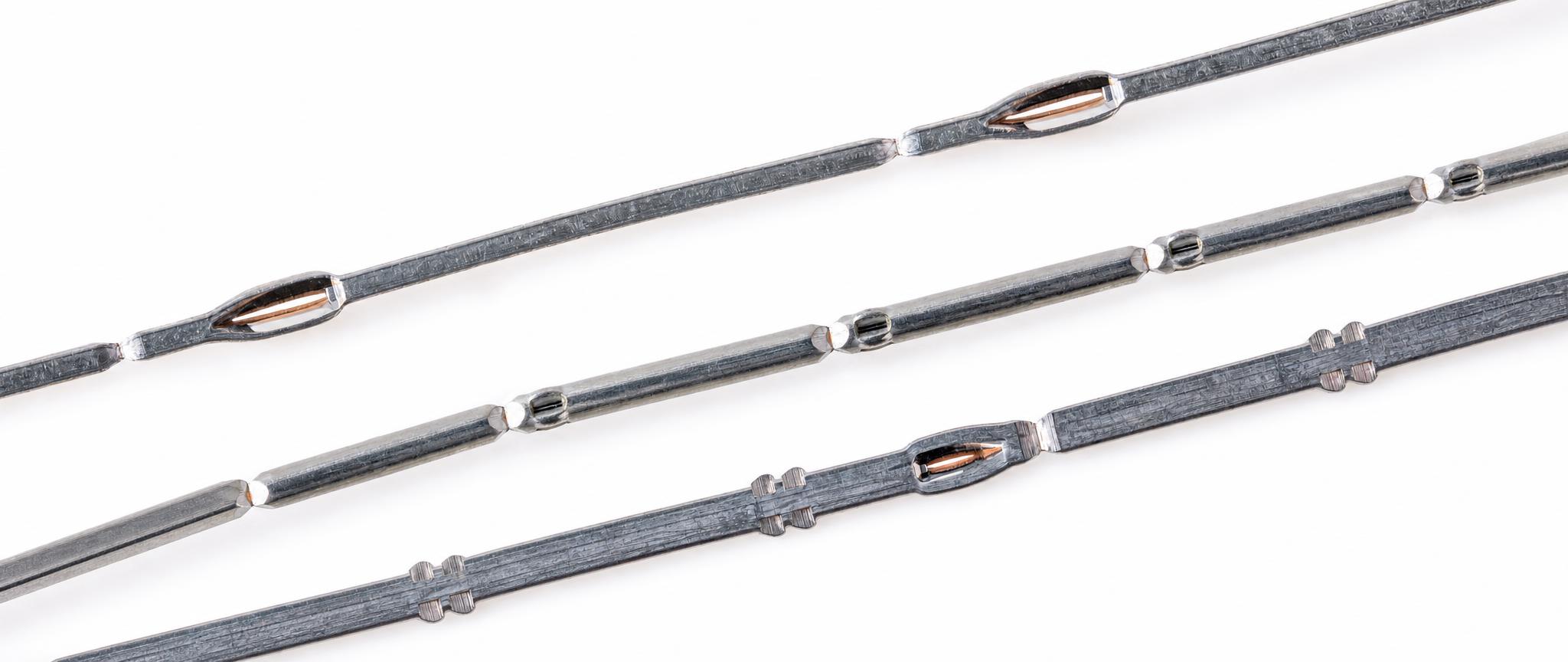
WIRE PIN CONNECTORS
Pin connector technology (pin insertion technology) is a highly effective method for creating electrical and mechanical connections in electronic assemblies. Unlike traditional off-the-shelf connectors, it offers customized, cost-efficient solutions for PCBs, plastic connectors, coil frames and more, tailored to your specific application.
What Is Pin Insertion Technology?
Pin connector technology involves inserting metal pins directly into components or printed circuit boards (PCBs) to establish electrical connections without soldering. The pins are designed with specific press-fit or specialty shapes to secure them mechanically and electrically for long-term performance.
This method:
- Eliminates the need for soldering (solderless connection),
- Reduces assembly time and costs,
- Improves reliability under harsh environments
Applications of Pin connectors
Pin connectors and pin insertion solutions are widely used across multiple sectors including:
- Automotive Electronics
High-reliability connections in control modules and sensor systems. - Robotics and motion
Reliable interconnections for control boards, communication modules, etc.
- Power electronics
Space-saving, solderless connectors for compact assemblies. - Medical Devices
Electrical modules requiring robust and maintenance-free connections.
Key Advantages of Pin Connector Systems
Cost-Effective and Customizable
No investments in molding. Pin connectors are significantly cheaper than purchasing complete connector assemblies. Customers purchase only the pins needed for the specific application.
Low Insertion Force
Optimized pin geometries and press-fit designs reduce mechanical stress during assembly, lowering production difficulty.
High Reliability & Durability
By eliminating soldering, pin connector systems avoid solder-related defects like cold joints or flux residue and deliver stable electrical contact under vibration and thermal cycling.
Adaptable to Hole Tolerances
Various pin shapes (smooth, star, wings/harpoon, compliant press-fit) allow secure retention even in holes with varying diameters.
Eco-Friendly Assembly
Solderless assembly reduces thermal stress and waste, making production cleaner and more environmentally friendly.

Pin Connector Types
Pin connectors vary by shape and functionality, each optimized for specific applications:
Smooth Pins
Basic pins with chamfered ends for general board or plastic insert applications.
Star Pins
Star-shaped for stronger retention and compensation of hole diameter tolerances; ideal for plated PCBs and press-in-paste processes.
Wings / Harpoon
Designed for plastic connectors with square holes; offers high mechanical resistance and is automotive-ready.
Press-Fit Pins
Compliant geometry allows pins to be pressed into holes to form a tight gas-tight electrical connection — a common solution instead of soldering.
Combined Shapes
Pins with multiple shaping features for complex PCB-to-PCB or PCB-to-plastic connections.
This simple-shaped type of pin has chamfers on both ends so that it can be used for connection purposes.
Application
Coil frame, printed circuits without metalized holes, over-molding, plastic components with drilled holes, metal components whose holes diameter has small tolerances.
Dimensions

|
Wire shape |
Square |
Round |
|||||||||
|---|---|---|---|---|---|---|---|---|---|---|---|
| A1 | 0.3 | 0.4 | 0.46 | 0.5 | 0.71 | 0.91 | 1 | 1.14 | 0.5 | 0.63 | 1 |
| B1 | 0.2 | 0.25 | 0.25 | 0.25 | 0.35 | 0.45 | 0.55 | 0.6 | 0.3 | 0.3 | 0.4 |
| Form | Size (mm) | A1 | B1 |
|---|---|---|---|
| Square | 0.3 | 0.3 | 0.2 |
| 0.4 | 0.4 | 0.25 | |
| 0.46 | 0.46 | 0.25 | |
| 0.5 | 0.5 | 0.25 | |
| 0.71 | 0.71 | 0.35 | |
| 0.91 | 0.91 | 0.45 | |
| 1 | 1 | 0.55 | |
| 1.14 | 1.14 | 0.6 | |
| Round | 0.5 | 0.5 | 0.3 |
| 0.63 | 0.63 | 0.3 | |
| 1 | 1 | 0.4 |
The Star pin is ideal for printed circuits with metalized holes to compensate holes diameter tolerances after drilling. It offers an excellent mechanical resistance and its shape is often used in “paste-in-pin and reflow” or “pin-in-paste and reflow” processes.
Its star shape, unlike the smooth pin, can be also used advantageously for round holes in plastic elements. When inserted, the smooth tip of a pin enters freely without any damage, while the star part provides its secure retention inside of a component thanks to its 4 peaks.
Application
Single- or double-sided printed circuits, coil frame, plastic connectors.
Dimensions:

| Wire shape | Square | |||||||||||||||||
|---|---|---|---|---|---|---|---|---|---|---|---|---|---|---|---|---|---|---|
| A1 | 0.3 | 0.3 | 0.4 | 0.4 | 0.46 | 0.46 | 0.5 | 0.5 | 0.63 | 0.63 | 0.71 | 0.71 | 0.91 | 0.91 | 1 | 1 | 1.14 | 1.14 |
| A2 | – | – | – | – | – | – | – | – | – | – | – | – | – | – | – | – | – | – |
| C | 0.5 | 0.55* | 0.63 | 0.7* | 0.73 | 0.8* | 0.78 | 0.84* | 0.97 | 1.07* | 1.17 | 1.24* | 1.5 | 1.55* | 1.73 | 1.8* | 1.93 | 2* |
| D | 1.1 | 1.1 | 1.1 | 1.1 | 1.5 | 1.5 | 1.5 | 1.5 | 1.5 | 1.5 | 1.5 | 1.5 | 1.5 | 1.5 | 1.5 | 1.5 | 1.5 | 1.5 |
| B1 | 0.2 | 0.2 | 0.25 | 0.25 | 0.25 | 0.25 | 0.25 | 0.25 | 0.3 | 0.3 | 0.35 | 0.35 | 0.55 | 0.55 | 0.55 | 0.55 | 0.6 | 0.6 |
| B2 | – | – | – | – | – | – | – | – | – | – | – | – | – | – | – | – | – | – |
| Wire shape | Rect. | Round | ||||||
| A1 | 0.63 | 0.5 | 0.5 | 1 | 1 | 1.5 | 1.5 | 1.5 |
| A2 | 1 | – | – | – | – | – | – | – |
| C | 1.27 | 0.66 | 0.7* | 1.32 | 1.4* | 1.78 | 1.78 | 1.78 |
| D | 1.5 | 0.8 | 0.8 | 1.5 | 1.5 | 1.5 | 1.5 | 1.5 |
| B1 | 0.3 | 0.3 | 0.3 | 0.4 | 0.4 | 0.7 | 0.8 | 0.9 |
| B2 | 0.5 | – | – | – | – | – | – | – |
| Wire shape | Size (mm) | A1 | A2 | C | D | B1 | B2 |
|---|---|---|---|---|---|---|---|
| Square | 0.3 | 0.3 | – | 0.5 | 1.1 | 0.2 | – |
| 0.3 | 0.3 | – | 0.55* | 1.1 | 0.2 | – | |
| 0.4 | 0.4 | – | 0.63 | 1.1 | 0.25 | – | |
| 0.4 | 0.4 | – | 0.7* | 1.1 | 0.25 | – | |
| 0.46 | 0.46 | – | 0.73 | 1.5 | 0.25 | – | |
| 0.46 | 0.46 | – | 0.8* | 1.5 | 0.25 | – | |
| 0.5 | 0.5 | – | 0.78 | 1.5 | 0.25 | – | |
| 0.5 | 0.5 | – | 0.84* | 1.5 | 0.25 | – | |
| 0.63 | 0.63 | – | 0.97 | 1.5 | 0.3 | – | |
| 0.63 | 0.63 | – | 1.07* | 1.5 | 0.3 | – | |
| 0.71 | 0.71 | – | 1.17 | 1.5 | 0.35 | – | |
| 0.71 | 0.71 | – | 1.24* | 1.5 | 0.35 | – | |
| 0.91 | 0.91 | – | 1.5 | 1.5 | 0.55 | – | |
| 0.91 | 0.91 | – | 1.55* | 1.5 | 0.55 | – | |
| 1 | 1 | – | 1.73 | 1.5 | 0.55 | – | |
| 1 | 1 | – | 1.8* | 1.5 | 0.55 | – | |
| 1.14 | 1.14 | – | 1.93 | 1.5 | 0.6 | – | |
| 1.14 | 1.14 | – | 2* | 1.5 | 0.6 | – | |
| Rect. | 0.63 | 0.63 | 1 | 1.27 | 1.5 | 0.3 | 0.5 |
| Round | 0.5 | 0.5 | – | 0.66 | 0.8 | 0.3 | – |
| 0.5 | 0.5 | – | 0.7* | 0.8 | 0.3 | – | |
| 1 | 1 | – | 1.32 | 1.5 | 0.4 | – | |
| 1 | 1 | – | 1.4* | 1.5 | 0.4 | – | |
| 1.5 | 1.5 | – | 1.78 | 1.5 | 0.7 | – | |
| 1.5 | 1.5 | – | 1.78 | 1.5 | 0.8 | – | |
| 1.5 | 1.5 | – | 1.78 | 1.5 | 0.9 | – |
Winged and harpoon pins suit square holes in plastic elements, guaranteeing excellent mechanical resistance of the pins in their seats thanks to its 2 peaks. At the same time the smooth tip of a pin enters freely without any damage.
These pins meet the requirements of automotive manufacturers for connector applications.
Application
Plastic connector.
Dimensions


| Wire shape | Square – wings | Square – harpoon | |
|---|---|---|---|
| A1 | 0.63 | 0.63 | 0.63 |
| C | 0.93 | 0.84 | 0.85 |
| D | 1 | 1 | 0.65 |
| B1 | 0.3 | 0.3 | 0.3 |
Pressfit flexible geometry matches components with various hole diameter tolerances. It can deal with deviations of + 0.10 to – 0 mm, in compliance with the IEC 352.5 standard.
Size difference between hole and pressfit zone leads to pressfit deformation during insertion. Subsequent сompression of a pin guarantees reliable connection, which doesn’t need to be soldered.
Application
Double-sided printed circuits. Particularly for automotive industry.
Dimensions

| Wire shape | Rectangular | Square | ||||||||
|---|---|---|---|---|---|---|---|---|---|---|
| A1 | 0.4 | 0.6 | 0.63 | 0.63 | 0.63 | 0.63 | 0.63 | 0.63 | 0.63 | 0.63 |
| A2 | 0.5 | 1 | 0.8 | – | – | – | – | – | – | – |
| C | 0.7 | 1.34 | 1.15 | 1.12 | 1.12 | 1.12 | 1.12 | 1.12 | 1.12 | 1.1 |
| D | 1.8 | 3 | 3 | 1.8 | 1.8 | 2.66 | 2.66 | 3 | 3 | 3 |
| B1 | 0.2 | 0.27 | 0.24 | 0.25 | 0.3 | 0.25 | 0.3 | 0.25 | 0.3 | 0.3 |
| B2 | 0.25 | 0.5 | 0.45 | – | – | – | – | – | – | – |
** D=1.8 – pressfit short D=2.66 – pressfit medium D=3 – pressfit long
| Wire shape | Column | A1 | A2 | C | D | B1 | B2 |
|---|---|---|---|---|---|---|---|
| Rectangular | Rect-1 | 0.4 | 0.5 | 0.7 | 1.8 | 0.2 | 0.25 |
| Rect-2 | 0.6 | 1 | 1.34 | 3 | 0.27 | 0.5 | |
| Rect-3 | 0.63 | 0.8 | 1.15 | 3 | 0.24 | 0.45 | |
| Square | Sq-1 | 0.63 | – | 1.12 | 1.8 | 0.25 | – |
| Sq-2 | 0.63 | – | 1.12 | 1.8 | 0.3 | – | |
| Sq-3 | 0.63 | – | 1.12 | 2.66 | 0.25 | – | |
| Sq-4 | 0.63 | – | 1.12 | 2.66 | 0.3 | – | |
| Sq-5 | 0.63 | – | 1.12 | 3 | 0.25 | – | |
| Sq-6 | 0.63 | – | 1.12 | 3 | 0.3 | – | |
| Sq-7 | 0.63 | – | 1.1 | 3 | 0.3 | – |
One pin can have several press shapes for direct interconnection of two elements. Pin length, shape and type is defined individually for each connection.
Application
Stacking of PCBs, stacking of PCBs with a plastic part.
How We Do Pin Insertion
Our structured process ensures reliable pin connector installation and quality documentation:
- Specification of Pin Parameters
Materials, coating, shape, type and length based on product requirements. - Tooling and Equipment Definition
Custom tools and equipment adapted to the application. - Simulation and FEA Analysis
Finite Element Analysis to model stresses and optimize insertion.
- Laboratory Testing
Press-in/pull-out force, contact resistance, and reliability reports. - Production of Insertion Equipment
Automated or semi-auto solutions tailored to volume and precision.